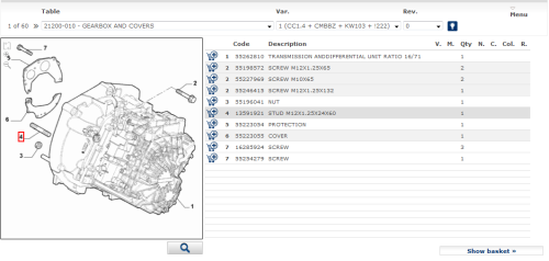
This page shows the part list (service BOM) and the technical drawing of the current illustration.
The technical drawing and the part list are “connected” so that when the cursor is over a part in the list, the position of the part is highlighted in the drawing with a red square (callout).
Fig. 21: Hot-spot
The explanation of various graphical components of the page is explained below.
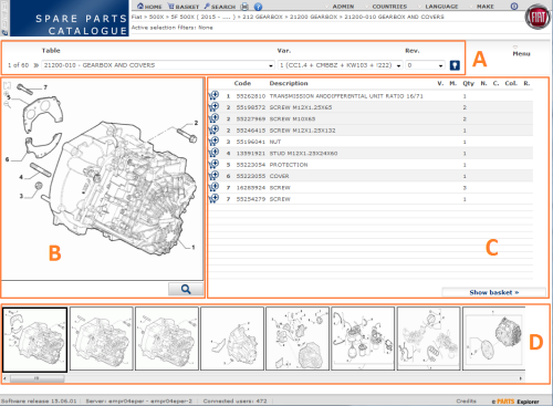
Fig. 22: Drawing
A – Table heading. Contains the following information
» The current and total number of illustrations of the current set.
» Arrows for accessing previous/next illustration (“<<” and “>>”).
» Title of current illustration and complete list of other available illustrations for the current selection.
»
List of variants of current illustration with
corresponding "usage pattern" (combination of features for which the
variant is valid, e.g. "CC1.4” = 1400 cc engine). It is possible to
display the description of features codes in the pattern by clicking on the
"bulb" icon = ![]() .
.
»
The icon ![]() is shown in cases where the features list and its
descriptions are too long to be shown it the list and by clicking on it the
complete pattern is shown with the features description.
is shown in cases where the features list and its
descriptions are too long to be shown it the list and by clicking on it the
complete pattern is shown with the features description.
» List of revisions.
B – Drawing. The following icons are available in the drawing canvas:
»
![]() = zoom-in: makes the drawing larger. Manually
select the portion of the drawing to zoom-in by right clicking and dragging the
mouse pointer.
= zoom-in: makes the drawing larger. Manually
select the portion of the drawing to zoom-in by right clicking and dragging the
mouse pointer.
»
![]() = zoom-out: makes the drawing smaller.
= zoom-out: makes the drawing smaller.
»
![]() = restore the drawing to its default zoom
factor.
= restore the drawing to its default zoom
factor.
»
![]() = opens the drawing in “fullscreen” mode
= opens the drawing in “fullscreen” mode
C – Part list.
This area displays detailed information about parts.
For every part the following information is available: position, part code, part description, usage pattern, production changes, usage quantity, notes, icon to access component list (only for assemblies), color usage, corresponding reman part.
Parts grayed out (displayed in a light gray color) are not “compatible” with the current vehicle features.
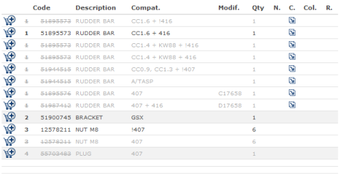
Fig. 23: List of spare parts
It is possible to display the description of feature codes by moving the cursor over the usage pattern field, as in the example below:
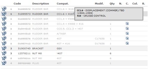
Fig. 24: Compatibility of spare parts
Columns in the part list
1 - Add to basket icon
This icon can be used to insert the part in the basket. Inside the icon a number represents the quantity of the part in the basket. Each click increment the counter by 1.
If the icon ![]() is displayed it means that the product
Is not available. In this case, place the mouse cursor over the icon for
additional information.
is displayed it means that the product
Is not available. In this case, place the mouse cursor over the icon for
additional information.
By clicking the 'Add to basket' button the system puts all the products selected in the table into the basket.
2 – Position number
Represents the position of the part in the corresponding drawings (callout). The parts is highlighted with a red square on the drawing when the mouse is moved over the part row.
3 – Product code (“Code”).
This is the product code. Click on the code to display the part details popup (see below).
4 – Description
Description of the part.
5 – Usage pattern
This field contains CoDeP based usage pattern. A pattern is composed by feature codes combined with the following logical operators:
‘,’ (comma) which means logical ‘or’
‘+’ (plus) which means ‘in combination with’
‘!’ (exclamation mark) which means 'without'
For example, the following pattern:
CC0.9, CC1.2 + !LL1
associated with a part means that the part can be used only for vehicles with a 900cc or 1200cc engine if “Trim Level” is NOT = 1 (naked)
Please refer to the CoDeP manual for a complete explanation of usage patterns defined in the FCA Bill Of Material.
By placing the mouse cursor over
the code the system will display the description. Use the ![]() icon at the side of the list of tables to
display the descriptions of all the codes used on the page.
icon at the side of the list of tables to
display the descriptions of all the codes used on the page.
6 - Changes
This field contains information about production changes made to the current vehicle model.
Each change is defined by a 4 digit number (e.g. 5584) preceded by the letter 'C' or 'D', where:
'C' indicates that the part has been dismissed (from the BOM) with the implementation of the change.
'D' indicates that the part has been introduced (in the BOM) with the implementation of the change.
The break point of a change can be defined as a production date or as an engine number or as a chassis number. By placing the mouse cursor over the change code the system will display both the change description and related break points.
7 – Quantity
Usage quantity.
8 –Notes
This field contains additional information of the part.
By placing the mouse cursor over the ![]() icon the system will display the contents as a
whole.
icon the system will display the contents as a
whole.
9 – Components
Whwn the ![]() icon is present then the part is an assembly.
By clicking on the icon
icon is present then the part is an assembly.
By clicking on the icon ![]() it is possible to access the components
of the assembly.
it is possible to access the components
of the assembly.
10 - Colors
This field may contain color usages for the part (e.g. a component in a specific color, i.e. “the part is applicable only if the vehicle has seats in red leather”)
D – List of drawings. This area displays the list of all drawings for the current illustrations set; depending previous selections, this area may contain:
» List of drawings of a group (e.g. 274)
» List of all drawings of a subgroup (e.g. 27404)
» List of all drawings of a specific illustration (variants and revisions) (e.g. 27404/01)
By moving the mouse over a drawing, the system displays a bigger preview of the graphic along with the number and description of the illustration and associated variants/revisions. This list may contain numbers images that can be displayed by using the sliding bar under the list.
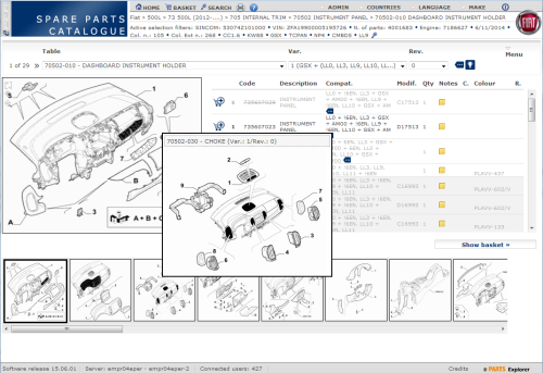
Fig. 25: Preview of the graphics